게임 개발/그래픽스
삼각형 레스터화
- -
좌표계
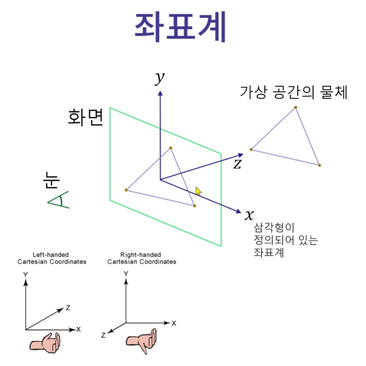
NDC(Normalized Device Coordinates)
http://www.directxtutorial.com/Lesson.aspx?lessonid=111-4-1
DirectXTutorial.com
First of all, I officially welcome you to Direct3D. I would like to teach you both the basics and the advanced topics of 3D programming. Whether you want to build your own engine, borrow one and modify it, or just buy one and use it, it is important that y
www.directxtutorial.com
Normalized Device Coordinates is a different type of coordinate system you may not be familiar with. It is used to measure relative positions on the monitor. However, these are not pixel coordinates.
The center of the screen is always 0, 0 in Normalized Device Coordinates. The top is always 1 and the bottom is always -1. The left side is always -1 and the right side is always 1.
Because these are relative coordinates, if the screen size changes, so do the coordinates.
레스터 좌표의 범위
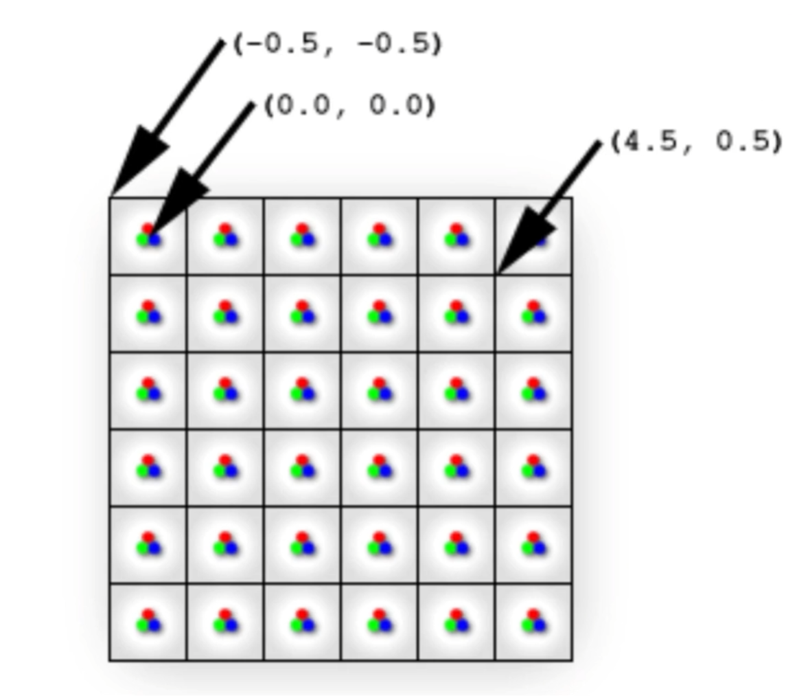
// 레스터 좌표의 범위 [-0.5, width - 1 + 0.5] x [-0.5, height - 1 + 0.5]
const float xScale = 2.0f / width;
const float yScale = 2.0f / height;
// NDC -> 레스터 화면 좌표계
// 주의: y좌표 상하반전
return vec2((pointNDC.x + 1.0f) / xScale - 0.5f,
(1.0f - pointNDC.y) / yScale - 0.5f);y 좌표를 왜 반전할까?
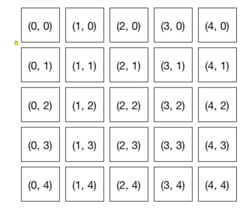
레스터 화면 좌표계는 y가 아래로 갈 수록 숫자가 커짐
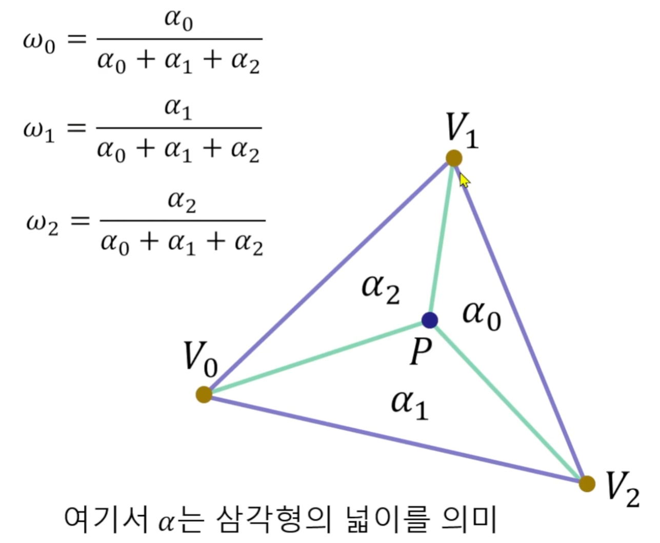
무게 중심 좌표 (barycentric coordinates)
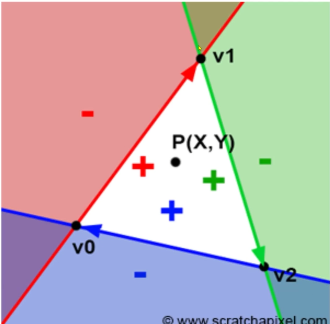
세개의 엣지에 대해서 모두 +가 나오면 삼각형 안이다.
코드 구현
#include "Rasterization.h"
#include <algorithm> // std::min(), ...
namespace hlab {
using namespace glm;
using namespace std;
Rasterization::Rasterization(const int &width, const int &height)
: width(width), height(height) {
// 삼각형을 구성하는 3개 정점들의 위치와 색 초기화
// 그릴 대상(여기서는 삼각형)과 그리는 알고리즘은
// 서로 다른 클래스로 분리하는 것이 좋겠지만
// 여기서는 모두 Rasterization 안에서 하겠습니다.
// 시계방향인지 반시계방향인지 주의
triangle.v0.pos = {0.0, 0.5, 1.0f};
triangle.v1.pos = {1.0, -0.5, 1.0f};
triangle.v2.pos = {-1.0, -0.5, 1.0f};
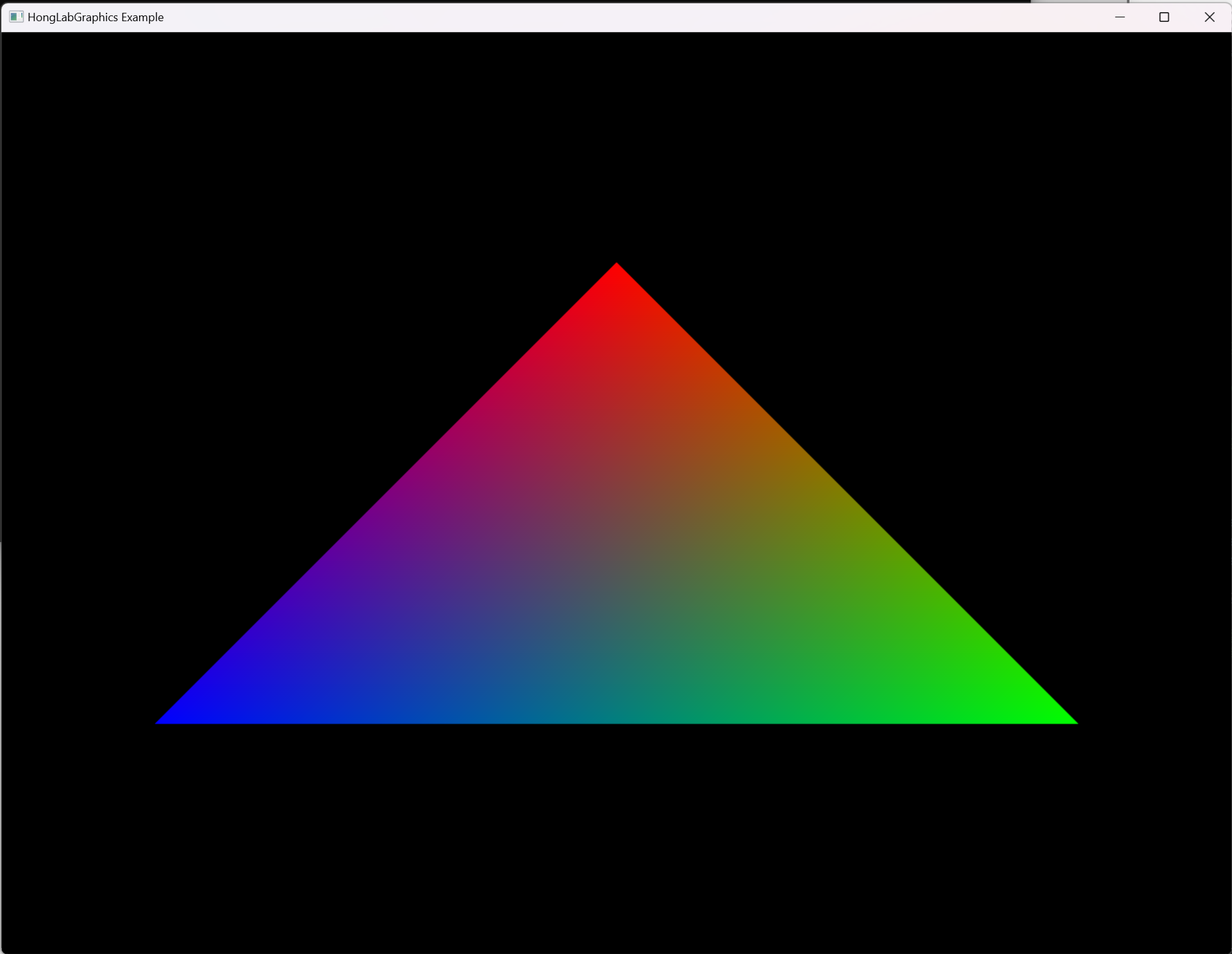
triangle.v0.color = {1.0f, 0.0f, 0.0f}; // Red
triangle.v1.color = {0.0f, 1.0f, 0.0f}; // Green
triangle.v2.color = {0.0f, 0.0f, 1.0f}; // Blue
}
// 3차원 좌표를 2차원 좌표로 변환
// 이번 예제에서는 정투영(Orthographic projection) 사용
vec2 Rasterization::ProjectWorldToRaster(vec3 point) {
// 월드 좌표계의 원점이 우리가 보는 화면의 중심이라고 가정
// NDC로 변환[-1, 1] x[-1, 1]
// NDC(Normalized Device Coordinates)
// NDC는 모니터의 실제 해상도와 상관 없이 정사각형이라는 점 주의
// 그림: http://www.directxtutorial.com/Lesson.aspx?lessonid=111-4-1
// 여기서는 width가 height보다 긴 경우만 고려
const float aspect = float(width) / height;
const vec2 pointNDC = vec2(point.x / aspect, point.y);
// 레스터 좌표의 범위 [-0.5, width - 1 + 0.5] x [-0.5, height - 1 + 0.5]
const float xScale = 2.0f / width;
const float yScale = 2.0f / height;
// NDC -> 레스터 화면 좌표계
// 주의: y좌표 상하반전
return vec2((pointNDC.x + 1.0f) / xScale - 0.5f,
            (1.0f - pointNDC.y) / yScale - 0.5f);
}
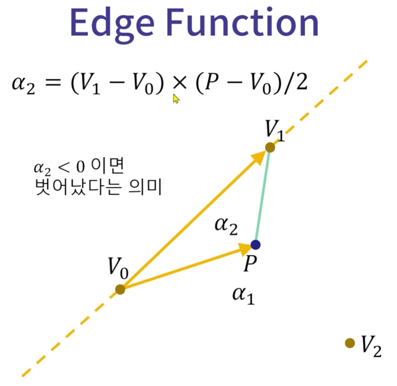
float Rasterization::EdgeFunction(const vec2 &v0, const vec2 &v1,
const vec2 &point) {
// 어떤 3차원 벡터 a = (ax, ay, az)와 b = (bx, by, bz)가 있을 때,
// a x b = (ay*bz - az*by, az*bx - ax*bz, ax*by - ay*bx) 이다.
// 앞에서는 glm::cross()로 간단히 계산
// 여기서는 3차원 정점들을 2차원 평면으로 투영했기 때문에
// az와 bz가 둘 다 0이라고 놓고 계산하면
// a x b = (0, 0, ax*by - ay*bx)
// 여기서 ax*by - ay*bx 반환
const vec2 a = v1 - v0;
const vec2 b = point - v0;
return a.x * b.y - a.y * b.x;
}
void Rasterization::Render(vector<vec4> &pixels) {
// DirectX에서 자동으로 처리해주는 부분들이기 때문에 흐름만 봐두셔도
// 충분합니다. 대부분 내부적으로 하드웨어 제조사에서 개발한 드라이버를
// 사용합니다.
// https://www.scratchapixel.com/lessons/3d-basic-rendering/rasterization-practical-implementation/rasterization-stage
// 삼각형을 하나만 그리는 경우입니다.
// 뒤에서 여러 개의 삼각형으로 확장해봅시다.
// World 좌표계에 정의된 정점의 좌표들을 Screen Raster 좌표계로 변환
// 변수 이름을 간단히 하기 위해서 v0, v1, v2를 사용했지만 좌표계가
// 다릅니다.
const auto v0 = ProjectWorldToRaster(triangle.v0.pos);
const auto v1 = ProjectWorldToRaster(triangle.v1.pos);
const auto v2 = ProjectWorldToRaster(triangle.v2.pos);
// Bounding box 찾기 (xMin, yMin, xMax, yMax)
// min(), max(), clamp()가 std::와 glm::에 모두 정의되어 있어서
// glm::min()과 같이 구체적으로 적어줬습니다.
// glm::min(), std::min() 중 어떤 것을 사용해도 상관 없습니다.
// std::min({a, b, c})는 a, b, c 중에서 가장 작은 값을 반환해줍니다.
const auto xMin = size_t(glm::clamp(
glm::floor(
std::min({v0.x, v1.x, v2.x})), 0.0f, static_cast<float>(width - 1)));
const auto yMin = size_t(glm::clamp(
glm::floor(
std::min({v0.y, v1.y, v2.y})), 0.0f, static_cast<float>(height - 1)));
const auto xMax = size_t(glm::clamp(
glm::ceil(
std::max({v0.x, v1.x, v2.x})), 0.0f, static_cast<float>(width - 1)));
const auto yMax = size_t(glm::clamp(
glm::ceil(
std::max({v0.y, v1.y, v2.y})), 0.0f, static_cast<float>(height - 1)));
//const auto xMin = 0.0f;
//const auto yMin = 0.0f;
//const auto xMax = static_cast<float>(width - 1);
//const auto yMax = static_cast<float>(height - 1);
// Bounding box에 포함되는 픽셀들의 색 결정
for (size_t j = yMin; j <= yMax; j++) {
for (size_t i = xMin; i <= xMax; i++) {
// Rasterizing a triangle
// 1. 픽셀이 삼각형에 포함되는지 확인
// 2. 픽셀의 색 결정
// 참고: A Parallel Algorithm for Polygon Rasterization
// 3D에서 bary centric coordinates 구하던 것과 동일한데
// 2D라서 z값을 0으로 고정하면 간단해짐
const vec2 point = vec2(float(i), float(j));
const float alpha0 = EdgeFunction(v1, v2, point);
const float alpha1 = EdgeFunction(v2, v0, point);
const float alpha2 = EdgeFunction(v0, v1, point);
if (alpha0 >= 0 && alpha1 >= 0 && alpha2 >= 0) {
// 픽셀의 색 결정
// 주의: 원근투영(perspective projection)에서는
// depth 값을 고려해서 보정해줘야 합니다.
const float sum = alpha0 + alpha1 + alpha2;
const float w0 = alpha0 / sum;
const float w1 = alpha1 / sum;
const float w2 = alpha2 / sum;
// Bary-centric coordinates를 이용해서 color interpolation
//const vec3 color = vec3(w0, w1, w2);
const vec3 color = (w0 * triangle.v0.color + w1 * triangle.v1.color + w2 * triangle.v2.color);
pixels[i + width * j] = vec4(color, 1.0f);
}
}
}
}
void Rasterization::Update() {
// 애니메이션 구현
}
} // namespace hlab'게임 개발 > 그래픽스' 카테고리의 다른 글
| 2차원 변환 (0) | 2023.11.07 |
|---|---|
| 원 그리기 (0) | 2023.11.07 |
| 레스터화(rasterization)가 빠른 이유 (0) | 2023.11.04 |
| 벡터와 포인트 (0) | 2023.11.04 |
| 투명한 물체와 빛의 굴절 (0) | 2023.11.02 |
Contents
소중한 공감 감사합니다